What are the Most Popular Sensors for Raspberry pi
What are the Most Popular Sensors for Raspberry pi
You can build some pretty amazing smart devices that can collect, process, and display data.
In this post, you will find a wide range of tutorials covering some of the most popular sensors that you can connect up to the Raspberry Pi. Each sensor is typically connected differently, so it’s important to double-check you’re building the circuit correctly.
Now each sensor typically involves a bit of Python code so, you’re able to extract the correct data from it. If you want to skip the coding part, then something like MyDevices Cayenne is a great way to build smart applications using a simple drag and drop interface.
There is just a ton of Raspberry Pi sensors that you’re able to hook up to your Pi. This includes sensors such as a photoresistor, temperature, humidity and so many more.
You can build a wide range of Raspberry Pi projects using sensors. It includes projects such as a weather station, home automation, data logging, motion detection and so much more.
Protecting your Pi is kinda crucial if you find it is in an area where it might get damaged. You may also just want it to look good. These are situations where a solid Raspberry Pi case would come in handy. There is also a wide range of other Pi accessories that you might be interested in for adding a bit more functionality to your Pi.
Now I would like to note down the some of the sensors for you-
1. Raspberry Pi UV Sensor using the VEML6075
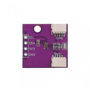
The VEML6075 UV Sensor is a dual-band sensor that senses both UVA (ultraviolet A/longwave) and UVB (ultraviolet B/shortwave) light bands. Its the most popular sensors for raspberry pi.
One of the best things about this sensor is that it provides its data over the I2C serial protocol, making it very simple to interact with. You can bundle this sensor with the many other sensors that work with the Raspberry Pi. For example, using a variety of sensors, you could build your own weather station.
Setting up your Raspberry Pi for the VEML6075 UV Sensor
1. Before we get started interacting with the VEML6075 UV sensor on our Raspberry Pi, there are a few things we must first do.
The first thing we need to do is ensure that our package list and all installed packages are at their latest available versions.
We can check and update by running the following commands.
sudo apt-get update
sudo apt-get upgrade
2. When your Raspberry Pi has finished updating, you can then proceed on to switching on I2C mode for the Pi’s serial interface.
We can do that by launching the Raspberry Pi configuration tool with the following command.
sudo raspi-config3. Within this tool, go ahead and select the “5 Interfacing Options” option.
Navigate the raspi-config tools menus by using the arrow keys, and the ENTER key.
4. Within interfacing options menu, go ahead and select the “P5 I2C” option.
When asked if you would like to enable the ARM I2C interface, select “<YES>“.
5. Enabling I2C won’t come into effect until you restart the Raspberry Pi. You can reboot the Raspberry Pi by running the following command.
sudo reboot6. With the I2C protocol now enabled on the Raspberry Pi, we can now proceed to install the packages that we will be relying on.
Install the various Python packages that we require by running the following command.
sudo apt-get install python3-dev python3-pip python3-smbus i2c-tools -y7. Now that all the required packages are installed we can use the “i2cdetect” program to see whether the Raspberry Pi can detect our VEML6075 UV sensor.
We can use the i2cdetect program by running the following command.
sudo i2cdetect -y 1This command will output a fair bit of information with many results being marked by hyphens. Within this result, you should see a number such as “10“.
If only hyphens appear in the result, that means the Raspberry Pi can not detect your UV sensor, check all your wiring then try rerunning the command.
If you see an error try re-enabling I2C again.
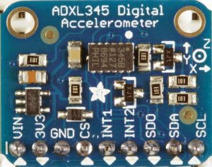
2. Raspberry Pi Accelerometer using the ADXL345
The ADXL345 is a low power, 3-axis (It tracks both X, Y and Z accelerations) MEMS accelerometer that utilizes the I2C and SPI serial interfaces.
For those who do not know, MEMS stands for Micro Electro Mechanical System. In the case of the accelerometer, this means that it has a microscopic component that is utilized to calculate the current acceleration being felt by the sensor.
The support of both I2C and SPI serial protocols makes it incredibly easy to use with our Raspberry Pi as we don’t require any additional hardware to interpret the data coming from the accelerometer.
Preparing your Raspberry Pi to Talk with the Accelerometer
1. Before we can get our Raspberry Pi to retrieve data from our ADXL345 Accelerometer, there are a few changes we must make to the Pi’s configuration.
Let’s first ensure that everything is up to date by running the following two commands.
sudo apt-get update
sudo apt-get upgrade
2. Once the Raspberry Pi has finished updating, we will need to go ahead and launch the Raspberry configuration tool so that we can enable I2C on the Raspberry Pi.
Run the following command to launch the raspi configuration tool.
sudo raspi-config3. On this screen, you need to head to the “5 Interfacing Options” menu.
You can navigate the raspi-config tools menus by using the arrow keys. Use the ENTER key to select particular options.
4. Now within the interfacing options menu go ahead and select “P5 I2C“.
When asked if you would like to enable the ARM I2C interface, select “<YES>“.
5. After enabling the I2C interface, you will need to restart your Raspberry Pi by running the following command.
sudo reboot6. Now that we have enabled I2C and restarted the Raspberry Pi, we can now proceed to install the packages that we will rely on to talk with our accelerometer.
Run the following command to install.
sudo apt-get install python3-dev python3-pip python3-smbus i2c-tools -y6. With all our required packages installed let’s now check to see whether our Raspberry Pi can see our ADXL345 Accelerometer.
We can do that by running the following command.
sudo i2cdetect -y 1From this command, you should see a fair bit displayed on the command line. Within this result, you should at least see a number such as “53“.
If nothing appears then make sure you have connected your ADXL345 Accelerometer to the Raspberry Pi correctly and that all solder points on the pins of the sensor are clean. If you see an error try re-enabling I2C again.
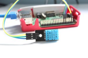
3. Raspberry Pi Humidity Sensor using DHT22
The DHT22 is a versatile and low-cost humidity sensor that can also calculate the temperature of an area.
This sensor has a relatively long transmission distance, allowing the sensor to transmit data through wires up to 20m away from the Raspberry Pi.
As a bonus, the DHT22 is a digital sensor with an inbuilt analog to digitalX converter. The converter makes it a lot easier to connect the sensor to the Raspberry Pi as you do not need to deal with any additional chips.
The biggest downside to the DHT11 and DHT22 sensors is that they are quite slow sensors. They have a sampling rate of once every second for the DHT11 and once every 2 seconds for the DHT22.
Preparing the Raspberry Pi to talk with the Humidity Sensor
1. Before we get started with programming a script for the Raspberry Pi humidity sensor, we must first ensure that we have the latest updates on our Raspberry Pi.
We can do this by running the following two commands to update both the package list and installed packages.
sudo apt-get update
sudo apt-get upgrade
2. With our package list now up to date, we need to go ahead and install both python 3 and pip. We will be using both of these packages to interact with our humidity sensor.
Install both python3-dev and python3-pip by running the command below.
sudo apt-get install python3-dev python3-pip3. Before we go ahead and install the DHT library, we should first run the following command to ensure we have the latest versions of the setuptools, wheel and pip python packages.
sudo python3 -m pip install --upgrade pip setuptools wheel4. Now using pip, we will go ahead and install Adafruit’s DHT library to the Raspberry Pi.
We will be using this Python library to interact with our DHT22 Humidity/Temperature sensor.
As a bonus, the library also supports the DHT11 and AM2302 humidity/temperature sensors making it a great library to learn how to utilize.
Run the following command to install the DHT library to your Raspberry Pi.
sudo pip3 install Adafruit_DHT5. In the next section of our Raspberry Pi humidity sensor tutorial, we will show you how you can put this library to use and utilize it within a python script to talk with the DHT22 sensor.
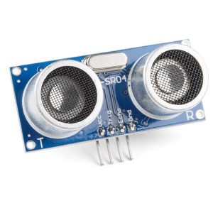
4. Raspberry Pi Distance Sensor using the HC-SR04
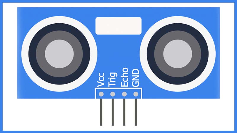
This one will go through showing you how to wire up the sensor with the Raspberry Pi as well as exploring how we can utilize the sensor also to read distance. I will be showing you how to wire the HC-SR04 sensor up to the Raspberry Pi, including how to wire a voltage divider as the circuit requires one to drop the 5v output from the sensor to 3.3v for the Raspberry Pi.
This is just one of many sensors you can use with your Raspberry Pi.
Utilizing your Raspberry Pi Distance Sensor
1. To utilize our Raspberry Pi Distance Sensor we luckily only have to program up a python script. Since we only use GPIO pins to interact with the distance sensor, there is no need to mess around with the raspi-config tool.
Before we begin writing our script, lets first make a folder to keep it. Run the following two commands on your Raspberry Pi to create the folder and change directory to it.
mkdir ~/distance_sensor/
cd ~/distance_sensor
2. Now that we are in our new directory, let’s begin writing our distance sensor python script by running the following command on the Raspberry Pi.
nano distance_sensor.py3. Within this file, write the following lines of code. We will explain the important parts of each block of code as we write it. Remember when writing in Python code that it is whitespace sensitive, so make sure that you retain the tabs that we have put in.
#!/usr/bin/python
import RPi.GPIO as GPIO
import time

try:
The first line tells the shell what we should be utilizing to run our Python file. Without it, there is no guarantee our file will be interpreted by Python.
We then proceed to import the two libraries that we need to write our script and interact with the distance sensor from our Raspberry Pi. The two libraries that we import are the following:
Rpi.GPIO – This is the package that allows us to control and interact with the GPIO pins, without this package we wouldn’t be able to talk with our distance sensor.
time – This package allows us to control time-related functions with the script. We mainly just use this to put the script to sleep and also time how long it takes to receive data back from the sensor.
Finally, we begin our try: statement, we cover the vast majority of the code within this to ensure that we clear the GPIO pins on exit.
      GPIO.setmode(GPIO.BOARD)

      PIN_TRIGGER = 7
      PIN_ECHO = 11

      GPIO.setup(PIN_TRIGGER, GPIO.OUT)
      GPIO.setup(PIN_ECHO, GPIO.IN)
On the first line here we set our GPIO mode to GPIO.BOARD, this means we are using the physical pin numbers and not the BCM numbers. We use this to ensure compatibility with our script as the BCM Numbers are not guaranteed to stay the same.
Next two lines we create two variables to store the physical pins that we have the trigger and echo wired to. We define them here to make it easy to change them without having to sift through the code continually.
Next we set up both our pins to either expect an output or an input. Our trigger pin is obviously an output pin as we need to ping this pin to start the sensor. The Echo pin is where we expect our data from, so we set this to receive input.
      GPIO.output(PIN_TRIGGER, GPIO.LOW)

      print "Waiting for sensor to settle"

      time.sleep(2)
The first line we set our PIN_TRIGGER GPIO Pin, so it doesn’t send out anything by setting it to “Low”. We do this to let our HC-SR04 sensor settle. This ensures we should be getting more consistent readings.
We then proceed to sleep the script for 2 seconds to ensure we give the distance sensor enough time to settle and don’t immediately start triggering it.
      print "Calculating distance"

      GPIO.output(PIN_TRIGGER, GPIO.HIGH)

      time.sleep(0.00001)

      GPIO.output(PIN_TRIGGER, GPIO.LOW)
Finally, we get to the piece of code which gets the HC-SR04 distance sensor to trigger. To do this, we need to first set our PIN_TRIGGER to high.
We then need to sleep the script for 1 nanosecond, the reason for this is that the HC-SR04 distance sensor requires a pulse of 1 nanosecond to trigger it.
Immediately after the sleep has completed, we set PIN_TRIGGER low again.
      while GPIO.input(PIN_ECHO)==0:
            pulse_start_time = time.time()
      while GPIO.input(PIN_ECHO)==1:
            pulse_end_time = time.time()

      pulse_duration = pulse_end_time - pulse_start_time

      distance = round(pulse_duration * 17150, 2)

      print "Distance:",distance,"cm"
First, we run a while loop to continually check if PIN_ECHO is low (0) if it is we continually set the pulse_start_time to the current time until it becomes high (1)
Once PIN_ECHO reads high, we set pulse_end_time to the current time. We do this until PIN_ECHO is set to low again.
These two loops allow us to calculate the time that it took for the ultrasonic pulse to be sent out and received back. Once we have both times, we just minus the two saved times to work out the duration.
With the pulse duration calculated we can work out the distance, it traveled since we know the rough speed of ultrasonic sound is 34300 cm/s.
Since the duration of the pulse is the time it took for the ultrasonic sound to hit an object and bounce back, we will just use half the speed to calculate the distance it traveled before returning. Doing this is a simpler calculation then calculating the distance with the full speed then dividing by 2.
So finally our distance is equal to the duration of the pulse, multiplied by 17150 cm/s.
finally:
      GPIO.cleanup()
These two final lines of code are quite crucial as it ensures an end to our try: statement and ensures that we run GPIO.cleanup() when the script is terminated in any way. Failing to do so will throw warnings when rerunning the script or any other script that makes use of the GPIO pins.
4. Once you have finished typing in all the code, you should end up with something that looks like what we have below.
#!/usr/bin/python
import RPi.GPIO as GPIO
import time

try:
      GPIO.setmode(GPIO.BOARD)

      PIN_TRIGGER = 7
      PIN_ECHO = 11

      GPIO.setup(PIN_TRIGGER, GPIO.OUT)
      GPIO.setup(PIN_ECHO, GPIO.IN)

      GPIO.output(PIN_TRIGGER, GPIO.LOW)

      print "Waiting for sensor to settle"

      time.sleep(2)

      print "Calculating distance"

      GPIO.output(PIN_TRIGGER, GPIO.HIGH)

      time.sleep(0.00001)

      GPIO.output(PIN_TRIGGER, GPIO.LOW)

      while GPIO.input(PIN_ECHO)==0:
            pulse_start_time = time.time()
      while GPIO.input(PIN_ECHO)==1:
            pulse_end_time = time.time()

      pulse_duration = pulse_end_time - pulse_start_time
      distance = round(pulse_duration * 17150, 2)
      print "Distance:",distance,"cm"

finally:
      GPIO.cleanup()
With the code entered in properly then you can save the file by pressing Ctrl + X then Y and pressing Enter.
5. Now that you have successfully written the script we can run it by running the following simple command on your Raspberry Pi.
python ~/distance_sensor/distance_sensor.py6. If everything is working correctly, you should get something like what is shown below in your terminal. Of course, the distance will be different to what we got.
Waiting for the sensor to settle
Calculating Distance
Distance: 26.69
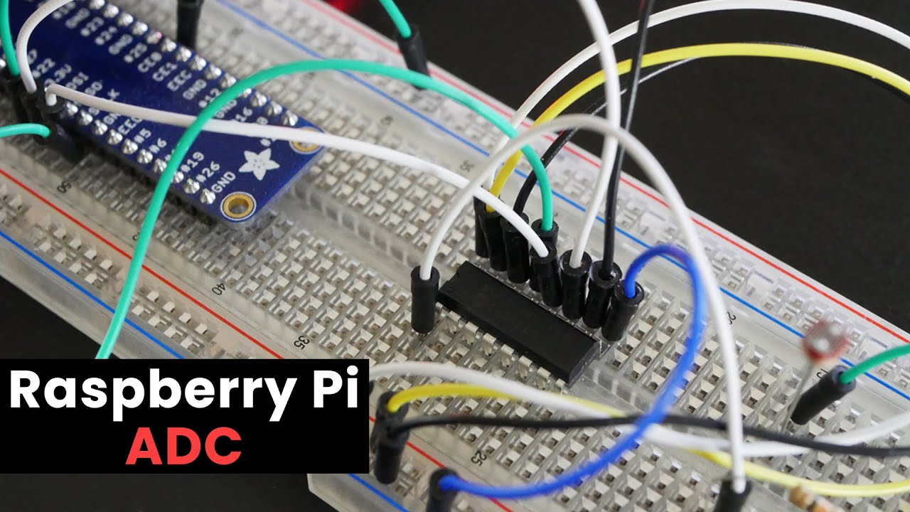
5. Raspberry Pi ADC(Analog To Digital Converter)
As you may already know the Pi doesn’t have any GPIO pins that are analog. This lack of analog pins makes connecting analog sensors a little more complex.
There are several solutions to the lack of Analog pins like the one I did in the Raspberry Pi LDR tutorial which involved using a capacitor to measure the resistance of the LDR (Light Dependent Resistor).
A better solution to this would be to use what is known as an analog digital converter (MCP3008). This chip involves a little bit of setting up which I will go into below.
The Code
The code for this is pretty simple but is also only handling just one input, the LDR. The code may be a little more complicated the more devices you add.
All the required packages for this tutorial should be installed by default on Raspbian.
git clone https://github.com/pimylifeup/Pi-ADC-Example-CodeYou will need to then move into the folder that contains our script by running the following line.
cd ./Pi-ADC-Example-CodeYou can now launch it by running the following line.
sudo python adc-code.pyYou can stop the script by press ctrl + c.
I will now just briefly explain the code. At the start of the code, we define the path of where Python is installed. After this, we import two packages that we will need. Time allows us to put the script to sleep (Add a delay). Spidev allows us to communicate with SPI devices, in this case, it is the MCP3008.
#!/usr/bin/python

import spidev
import time
Next, we define the variables and create our SPIdev object. We create two variables first being a delay in milliseconds. Alter this if you want there to be a more considerable amount of time between updates. Next is the channel our LDR is located on, this is channel 0/pin 1.
Finally, we create the SPIdev object. This object allows us to get the values we need from the device connected the SPI enabled pins.
#Define Variables
delay = 0.5
ldr_channel = 0

#Create SPI
spi = spidev.SpiDev()
spi.open(0, 0)
Next, we have the readadc function in which we do a couple of things. Firstly, we check the parameter value to make sure it’s between 0 and 7, if not then return -1. If it is, we then proceed to get the value from the channel specified and then return the value.
def readadc(adcnum):
    # read SPI data from the MCP3008, 8 channels in total
    if adcnum > 7 or adcnum < 0:
        return -1
    r = spi.xfer2([1, 8 + adcnum << 4, 0])
    data = ((r[1] & 3) << 8) + r[2]
    return data
Lastly we have a while loop that continues until you force quit it by pressing ctrl + c. The first thing we do is call the readadc function with the ldr_channel variable as the parameter.
Once we get the value, back we simply print it. The %d refers to a decimal value; we then have our variable after the print statement. You can print multiple values per line by doing something like this. print '%s %d' % (name, number)
After we have printed the data, we delay the script for whatever the delay time is set to. By default, it is set for half a second.
while True:
    ldr_value = readadc(ldr_channel)
    print "---------------------------------------"
    print("LDR Value: ".ldr_value)
    time.sleep(delay)
I hope this has helped you understand the code a little. As I mentioned above, you can download the full script over at the GitHub.
If you do come across any problems, then feel free to mention them in the comments below.
Using the ADC with Raspberry Pi Cayenne
I will now quickly go through the steps to set up the MCP3008 with Cayenne. I will also go through how to setup the LDR.
If you haven’t already set up Cayenne, then be sure to follow my guide on how to install Raspberry Pi Cayenne. The tutorial goes through the steps to getting it installed and most the basics you need to know for creating your very own smart applications.
1. To begin first go to add new and then select device from the drop-down box.
2. Then either search or select analog converter.
3. In this list select the MCP3008
4. Now select the Raspberry Pi and then SPI Chip-Select 0
5. This selection will now bring up a screen that shows you all the values of the channels.
Now to add the LDR, the process is pretty much the same, but I will go through it anyway.
1. Go back up to add new and then select device.
2. Find or select the photoresistor (Luminosity Sensor).
3. For this one select your Raspberry Pi, your preferred widget (I went graph), then select the MCP3008 for the analog converter and finally channel 0 for the channel.
4. This sensor should now add without any issue. It will now produce a graph from the values it gets from the analog converter.
Now you can pretty much follow this same process for any analog device.
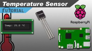
6. Raspberry Pi Temperature Sensor using DS18B20
Like most of the sensor tutorials, the process of setting up this sensor is pretty straightforward and consists of a basic circuit and some code.
You can use a DS18B20 waterproof sensor, and this probe can provide temperatures over a one-wire interface. Even better this is waterproof making it perfect if you need to use the sensor in a wet environment.
There are many other temperature sensors that you can use with your Raspberry Pi but in this, I will be focusing on the DS18B20.
The Raspberry Pi Temperature Sensor Code
The code for setting up the temperature sensor is a little more complicated than the circuit itself. This complexity is just because of the way we need to handle the data that comes from the sensor.
We will be using python here. As it is a must known language if you are techno enthusiast, I would recommend you to learn it.
Before we make the Python script, we first need to set up the Pi so it can read data from the sensor. To do this, we need to add OneWire support.
1. To add support for OneWire, we first need to open up the boot config file, and this can be done by running the following command.
sudo nano /boot/config.txt2. At the bottom of this file enter the following.
dtoverlay=w1-gpio3. Once done save & exit by pressing ctrl x and then y. Now reboot the Pi by running the following command.
sudo reboot4. You can skip to downloading the code onto the Pi or follow the next few steps to check that the sensor is actually working.
5. Once the Raspberry Pi has booted back up, we need to run modprobe so we can load the correct modules.
sudo modprobe w1-gpio
sudo modprobe w1-therm
6. Now change into the devices directory and use ls to see the folders and files in the directory.
cd /sys/bus/w1/devices
ls
7. Now run the following command, change the numbering after cd to what has appeared in your directory by using the ls command. (If you have multiple sensors there will be more than one directory)
cd 28-000007602ffa8. Now run the following command.
cat w1_slave9. This command should output data but as you will notice it is not very user-friendly.
The first line should have a YES or NO at the end of it. If it is YES, then a second line with the temperature should appear. This line will look similar to something like t=12323, and you will need to do a bit of math to make this a usable temperature that we can understand easily. For example, Celsius you simply divide by 1000.

Now it’s time to move onto the Python script.
I’ll briefly explain the code below if you want to learn more about it.
To begin the Python script, we import three packages, OS, Glob and time.
Next, we run the modprobe commands, and these commands are the same as what we used before.
We declare three different variables that will point to the location of our sensor data. You shouldn’t have to change any of these.
import os
import glob
import time

os.system('modprobe w1-gpio')
os.system('modprobe w1-therm')

base_dir = '/sys/bus/w1/devices/'
device_folder = glob.glob(base_dir + '28*')[0]
device_file = device_folder + '/w1_slave'
In the read_temp_raw function we open up the file that contains our temperature output. We read all the lines from this and then return it so the code that has called this function can use it. In this case the read_temp function calls this function.
def read_temp_raw():
    f = open(device_file, 'r')
    lines = f.readlines()
    f.close()
    return lines
In the read_temp function we process the data from the read_temp_raw function. We first make sure that the first line contains YES. This means there will be a line with a temperature in it.
If there is a temperature we then find the line with t= by using lines[1].find('t='). Lines[1] means we’re looking at the 2nd element in the array, in this case, the 2nd line.
Once we have the line we simply get all the numbers that are after the t= and this is done at lines[1][equals_pos+2:]. Equals_pos is the start position of the temperature (t), and we add 2 to the position, so we only get the actual temperature numbers.
We then convert the number into both a Celsius and Fahrenheit temperature. We return both of these to the code that called this function. This function is the print located in the while loop.
def read_temp():
    lines = read_temp_raw()
    while lines[0].strip()[-3:] != 'YES':
        time.sleep(0.2)
        lines = read_temp_raw()
    equals_pos = lines[1].find('t=')
    if equals_pos != -1:
        temp_string = lines[1][equals_pos+2:]
        temp_c = float(temp_string) / 1000.0
        temp_f = temp_c * 9.0 / 5.0 + 32.0
        return temp_c, temp_f
The while loop is always true so it will run forever until the program is interrupted by an error or by the user cancelling the script. It simply calls the read_temp within the print function. The print function allows us to see the output on our screen. The script is then put to sleep for 1 second every time it has read the sensor.
while True:
	print(read_temp())
time.sleep(1)7.Raspberry Pi Light Sensor using a simple LDR
This photoresistor is yet another sensor that I will be looking at incorporating into future projects such as a light-activated alarm clock.
The Raspberry Pi Light Sensor Circuit
The circuit we are going to make for this tutorial is super simple and is great for anyone who is just starting out with circuitry.
Light Dependent Resistor (LDR)
The light-dependent resistor or also known as the LDR sensor is the most important piece of equipment in our circuit. Without it, we wouldn’t be able to detect whether it is dark or light.
In the light, this sensor will have a resistance of only a few hundred ohms while in the dark, it can have a resistance of several megohms.
Capacitor
The capacitor in our circuit is included, so we’re able to measure the resistance of the LDR sensor.
A capacitor essentially acts like a battery, charging up while receiving power and then discharging when no longer receiving power. Using this in series with the LDR, we can work out how much resistance the LDR is giving out, thus being able to tell whether it is light or dark.
Circuit Assembly
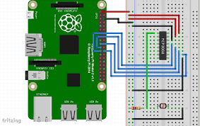
To get the light sensor circuit built correctly, follow the steps below. Alternatively, check out the circuit diagram right underneath the steps.
1. First, connect pin #1 (3v3) to the positive rail on the breadboard.
2. Next, connect pin #6 (ground) to the ground rail on the breadboard.
3. Now place the LDR sensor onto the board and have a wire go from one end to the positive rail.
4. On the other side of the LDR sensor, place a wire leading back to the Raspberry Pi. Hook this to pin #7.
5. Finally, place the capacitor from the wire to the negative rail on the breadboard. Make sure you have the negative pin of the capacitor in the negative rail.
We’re now ready to move onto the Python code. If you have any trouble with the circuit, refer to the diagram below.
The Light Sensor Code
The code for this project is pretty simple and will tell us roughly whether it is light, shady, or completely dark.
The biggest problem we face with this circuit is the fact that the Pi doesn’t have any analogue pins. They’re all digital, so we can’t accurately measure the variance in resistance on our input.
This lack of analogue pins wasn’t a problem in the motion sensor tutorial since the output from it was either high or low (Digital). Instead, we will measure the time it takes for the capacitor to charge and send the pin high. This method is an easy but inaccurate way of telling whether it is light or dark.
To begin, we import the GPIO package that we will need so that we can communicate with the GPIO pins.
We also import the time package, so we’re able to put the script to sleep for when we need to.
#!/usr/local/bin/python

import RPi.GPIO as GPIO
import time
We then set the GPIO mode to GPIO.BOARD, and this means all the numbering we use in this script will refer to the physical numbering of the pins.
Since we only have one input/output pin, we only need to set one variable. Set this variable to the number of the pin you have acting as the input/output pin.
GPIO.setmode(GPIO.BOARD)

#define the pin that goes to the circuit
pin_to_circuit = 7
Next, we have a function called rc_time that requires one parameter, which is the pin number to the circuit. In this function, we initialize a variable called count, and we will return this value once the pin goes to high.
We then set our pin to act as an output and then set it to low. Next, we have the script sleep for 10ms.
After this, we then set the pin to become an input, and then we enter a while loop. We stay in this loop until the pin goes to high, this is when the capacitor charges to about 3/4.
Once the pin goes high, we return the count value to the main function. You can use this value to turn on and off an LED, activate something else, or log the data and keep statistics on any variance in light.
def rc_time (pin_to_circuit):
    count = 0

    #Output on the pin for
    GPIO.setup(pin_to_circuit, GPIO.OUT)
    GPIO.output(pin_to_circuit, GPIO.LOW)
    time.sleep(0.1)

    #Change the pin back to input
    GPIO.setup(pin_to_circuit, GPIO.IN)

    #Count until the pin goes high
    while (GPIO.input(pin_to_circuit) == GPIO.LOW):
        count += 1

    return count

#Catch when script is interrupted, cleanup correctly
try:
    # Main loop
    while True:
        print(rc_time(pin_to_circuit))
except KeyboardInterrupt:
    pass
finally:
    GPIO.cleanup()